
Industry News
Curation by industry experts
Hot Articles
Popular Tags
Why do gear reducers fail under variable loads?
Gear reducers rarely fail without warning, but variable loads can turn small alignment errors, lubrication gaps, and bearing wear into costly downtime. For after-sales maintenance teams, understanding how shock loads, torque spikes, thermal cycling, and duty-cycle changes affect gear reducers is essential to diagnosing failures before they escalate. This article explains the common failure mechanisms under fluctuating operating conditions and highlights practical inspection points that help extend service life, reduce repeat repairs, and improve reliability in demanding industrial transmission systems.
In field service work, the difficult failures are often not caused by one visible defect. They develop through 3–5 interacting factors: load variation, lubricant condition, shaft alignment, bearing stiffness, and installation practice. When these factors drift together, even correctly selected gear reducers can move from normal wear to rapid damage.
How variable loads stress gear reducers in real applications
Variable load means the reducer does not operate at one stable torque, speed, or temperature. It may see repeated starts, conveyor jams, reversing cycles, intermittent overloads, or production batches changing every 4–8 hours.
For after-sales maintenance personnel, the key question is not only whether the nominal motor power is correct. The more important issue is whether peak torque, shock frequency, and duty cycle exceed the mechanical safety margin.
Shock loads and torque spikes
A gear reducer may tolerate a short overload, but repeated torque spikes change the contact pattern on gear teeth. Impacts above 150% of rated torque, even for seconds, can initiate micro-pitting on hardened surfaces.
These spikes are common in crushers, mixers, elevators, indexing tables, packaging lines, and conveyors with uneven material feed. A 10-second jam event may leave no visible damage, but 50 events per shift can accelerate fatigue.
Thermal cycling under intermittent duty
Variable loads also create temperature swings. If the reducer rises from 35°C to 85°C several times per day, seals, lubricant viscosity, and bearing clearances all change repeatedly.
Thermal cycling is especially damaging where equipment starts cold, reaches high load quickly, then stops before oil stabilizes. This pattern weakens lubrication film and increases condensation risk during long idle periods.
The table below summarizes practical load patterns that field teams commonly encounter when investigating failed gear reducers in automated production, heavy equipment, and general industrial transmission systems.
The main lesson is that rated torque alone is not enough. Maintenance teams should record at least 3 operating values: peak load, starts per hour, and casing temperature. These numbers often explain why repeat repairs occur.
Common failure mechanisms under fluctuating torque
When gear reducers work under variable loads, failures usually appear in gears, bearings, seals, shafts, or lubrication systems. Each failure leaves different evidence, and the evidence should guide the repair decision.
Gear tooth fatigue and micro-pitting
Micro-pitting appears as grey staining or fine surface roughness on tooth flanks. It often starts when contact stress rises beyond the lubrication film’s ability to separate metal surfaces.
Under steady load, a correct lubricant may protect the tooth mesh. Under variable load, film thickness changes rapidly, especially at low speed below 20 rpm or during repeated acceleration.
Bearing wear and misalignment amplification
Bearings inside gear reducers carry radial and axial forces that change with load direction. A small mounting deviation of 0.1–0.3 mm can become serious when torque reverses frequently.
As bearing clearance increases, gear mesh alignment changes. This creates a damaging loop: load variation increases bearing wear, bearing wear changes tooth contact, and poor contact increases vibration.
Seal failure and lubricant contamination
Seals are often blamed after oil leakage appears, but leakage may be a symptom rather than the root cause. Pressure pulses, shaft runout, heat, and dirty breathers can overload sealing lips.
If water or abrasive dust enters the housing, lubricant can lose protective function quickly. In harsh workshops, oil sampling every 3–6 months is more reliable than visual inspection alone.
Field clues that point to the root cause
- A whining sound that rises with speed often indicates tooth mesh wear or incorrect contact pattern.
- A rumbling sound at low speed may indicate bearing damage, especially after overload events.
- Dark oil with burnt odor suggests overheating, oxidation, or operation beyond the intended duty cycle.
- Metal particles on a magnetic plug indicate active wear and should trigger immediate inspection.
- Oil leakage after temperature rise may indicate blocked ventilation, overfilling, or seal hardening.
A useful rule for service teams is to separate symptoms into 2 groups: damage evidence and operating evidence. Both are needed before deciding whether to replace parts, correct installation, or upgrade the reducer.
Inspection workflow for after-sales maintenance teams
A structured inspection avoids unnecessary replacement and helps identify repeat-failure risks. For gear reducers under variable loads, the process should cover operating history, mechanical condition, lubrication, alignment, and duty cycle.
A 6-step diagnostic process
- Confirm the actual load profile, including starts per hour, shock events, and operating hours per day.
- Measure surface temperature after 30–60 minutes under normal production load.
- Check oil level, oil color, viscosity grade, contamination, and replacement interval.
- Inspect coupling alignment, foundation bolts, soft foot, and shaft runout.
- Evaluate vibration trend, abnormal noise, backlash, and bearing condition.
- Compare findings with the reducer’s service factor and application requirements.
This process is practical for both warranty investigation and paid maintenance. It also creates a consistent record that helps distributors and end users agree on corrective actions.
The following table provides a field-ready checklist. It is suitable for maintenance reports where teams must separate normal wear from overload, contamination, or installation-related damage.
The strongest indicator is trend change. A single temperature reading may be harmless, but a 20°C rise combined with darker oil and increasing vibration suggests active deterioration.
Selection and upgrade factors when failures repeat
When the same reducer location fails every 6–12 months, maintenance alone is usually not enough. The application may require a different service factor, gear geometry, bearing arrangement, or lubrication method.
Service factor and duty cycle matching
Service factor is a practical bridge between catalog rating and real operating conditions. Applications with impact loads, frequent starts, or 24-hour operation may require a factor above 1.5.
If the original gear reducers were selected only by motor power, revisit the torque calculation. Consider load inertia, acceleration time, peak torque, ambient temperature, and daily operating hours.
Lubrication strategy and oil grade
Oil viscosity must match speed, temperature, and load. Too thin an oil weakens film strength; too thick an oil increases churning losses and heat, especially at high input speeds.
For demanding variable-load duty, many facilities adopt 3 controls: correct viscosity grade, scheduled sampling, and controlled filling level. Overfilling can raise temperature as quickly as underfilling damages gears.
Upgrade questions before replacement
- Has the driven machine changed capacity, speed, product density, or production cycle in the last 12 months?
- Is the reducer exposed to washdown, dust, outdoor temperature swings, or high ambient heat above 40°C?
- Does the application need a torque limiter, soft starter, inverter tuning, or mechanical damping?
- Can the baseplate, coupling, and shaft arrangement support higher torque without transmitting misalignment?
- Would a larger frame size reduce thermal load and improve bearing life in continuous operation?
These questions help after-sales teams shift from part replacement to reliability improvement. In many cases, the correct solution is not the largest reducer, but the best-matched transmission package.
Maintenance practices that reduce variable-load failures
Preventive maintenance for gear reducers should be simple enough for daily execution but detailed enough to catch early damage. A balanced plan combines operator checks, technician inspection, and scheduled oil analysis.
Recommended inspection frequency
For normal service, weekly visual checks and quarterly mechanical checks are common. For high-shock or 24/7 duty, inspections may need to move to daily observation and monthly detailed review.
The maintenance plan should include at least 5 records: oil level, leakage, temperature, noise, and vibration. Without records, teams cannot distinguish random fluctuation from deterioration.
Installation discipline after repair
Many repaired reducers fail again because installation conditions remain unchanged. Foundation looseness, misaligned couplings, incorrect belt tension, and unsupported overhung loads can overload new bearings quickly.
After replacement, run the reducer unloaded for 20–30 minutes when possible, then gradually apply load. Check temperature, leakage, and noise before returning the line to full-speed production.
Practical maintenance priorities
- Keep lubricant clean, correctly graded, and filled to the manufacturer’s specified level.
- Control shock loads through process adjustment, torque limiting, or drive ramp optimization.
- Maintain coupling alignment and check foundation bolts after the first 8–24 hours of operation.
- Protect breathers and seals from dust, water spray, and chemical contamination.
- Trend vibration and temperature rather than relying only on one-time measurements.
These steps are low-cost compared with downtime. They also provide the evidence needed for accurate warranty review, spare-part planning, and purchasing decisions for future gear reducers.
Commercial value of reliable failure diagnosis
For distributors, service providers, and maintenance departments, reducer diagnosis is not only a technical task. It affects spare inventory, repair quotation accuracy, delivery planning, and customer confidence.
A well-documented investigation can reduce unnecessary replacement, clarify whether failure came from overload or maintenance gaps, and support better component selection for the next purchasing cycle.
How GPT-Matrix supports technical decision-making
GPT-Matrix focuses on industrial power transmission, motion control, mechanical joints, and sealing technologies. Its intelligence framework connects field symptoms with material science, tribology, and transmission system logic.
For after-sales maintenance teams, this means access to decision-oriented knowledge: failure mechanisms, inspection logic, reliability trends, and commercial insights for long-life, low-maintenance components.
When to seek additional support
- The same reducer position has failed more than twice within 18 months.
- Oil analysis shows repeated metal particles, water ingress, or abnormal oxidation.
- Temperature, noise, and vibration increase together after production capacity changes.
- The current reducer selection lacks clear service factor or duty-cycle documentation.
Variable loads do not automatically destroy gear reducers, but they expose every weak point in the transmission chain. Shock torque, thermal cycling, lubrication gaps, bearing wear, and installation errors must be reviewed together.
After-sales maintenance teams that document load profiles, trend operating data, and inspect with a structured workflow can reduce repeat repairs and improve reliability across demanding industrial systems.
To explore deeper transmission reliability insights, maintenance evaluation methods, or component selection guidance for variable-load applications, contact GPT-Matrix to learn more solutions or request a tailored technical consultation.
Recommended News
Selecting Split Mechanical Seals for Large Pumps: Shaft Size, Pressure, and Downtime
Split mechanical seals for large pumps: evaluate shaft size, pressure, fluid duty, and installation access to reduce downtime and improve sealing reliability.

How to Evaluate an Automated Production Supplier for a High-Uptime Manufacturing Line
Automated production supplier evaluation guide: assess uptime, maintainability, lifecycle cost, service support, and acceptance criteria for reliable manufacturing.
Designing Reliable Mechanical Transmissions: Load, Lubrication, and Fatigue Factors
Reliability in mechanical transmission design starts with real duty cycles. Explore load, lubrication, alignment, and fatigue factors for longer service life.
How to Define Load Requirements in Component Specifications for Safe Selection
Component specification guidance for load requirements: define load paths, duty cycles, peaks, environmental limits, and safety margins for safer component selection.
How to Evaluate Precision Engineered Transmissions for High-Load Industrial Systems
Precision engineered transmissions for high-load systems: learn how to assess load profiles, thermal limits, sealing, stiffness, and lifecycle reliability for smarter industrial decisions.
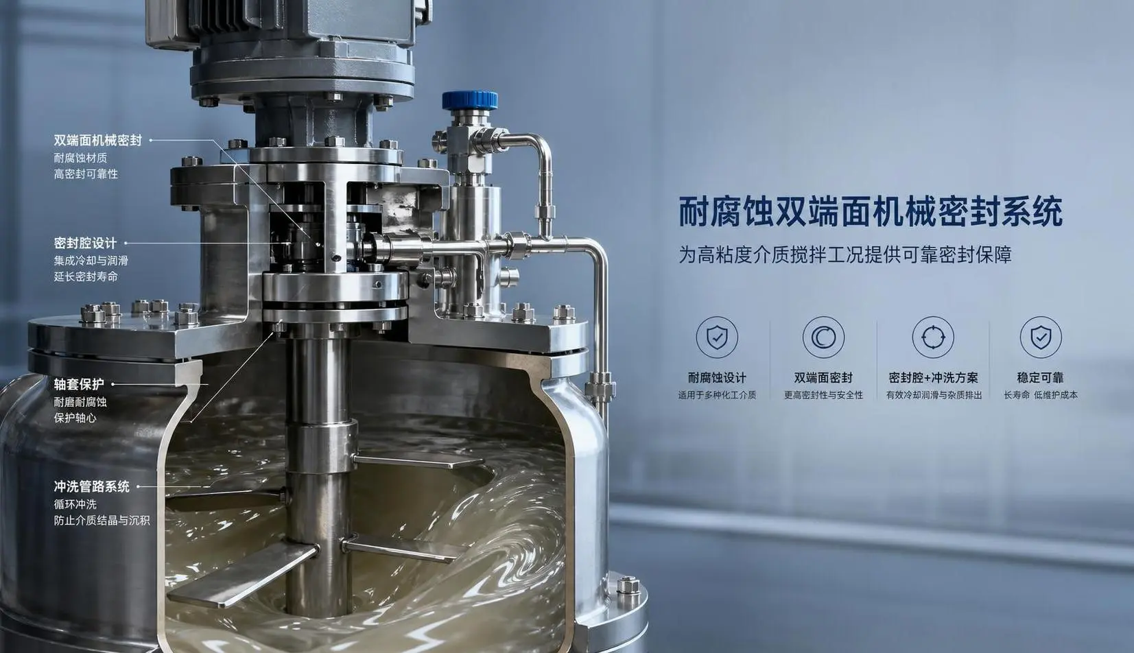
How to Select Mechanical Seals for Mixers in Corrosive or High-Viscosity Processes
Mechanical seals for mixers in corrosive or high-viscosity processes require the right materials, design, and support system. Learn how to choose a reliable seal and reduce leaks, downtime, and maintenance.
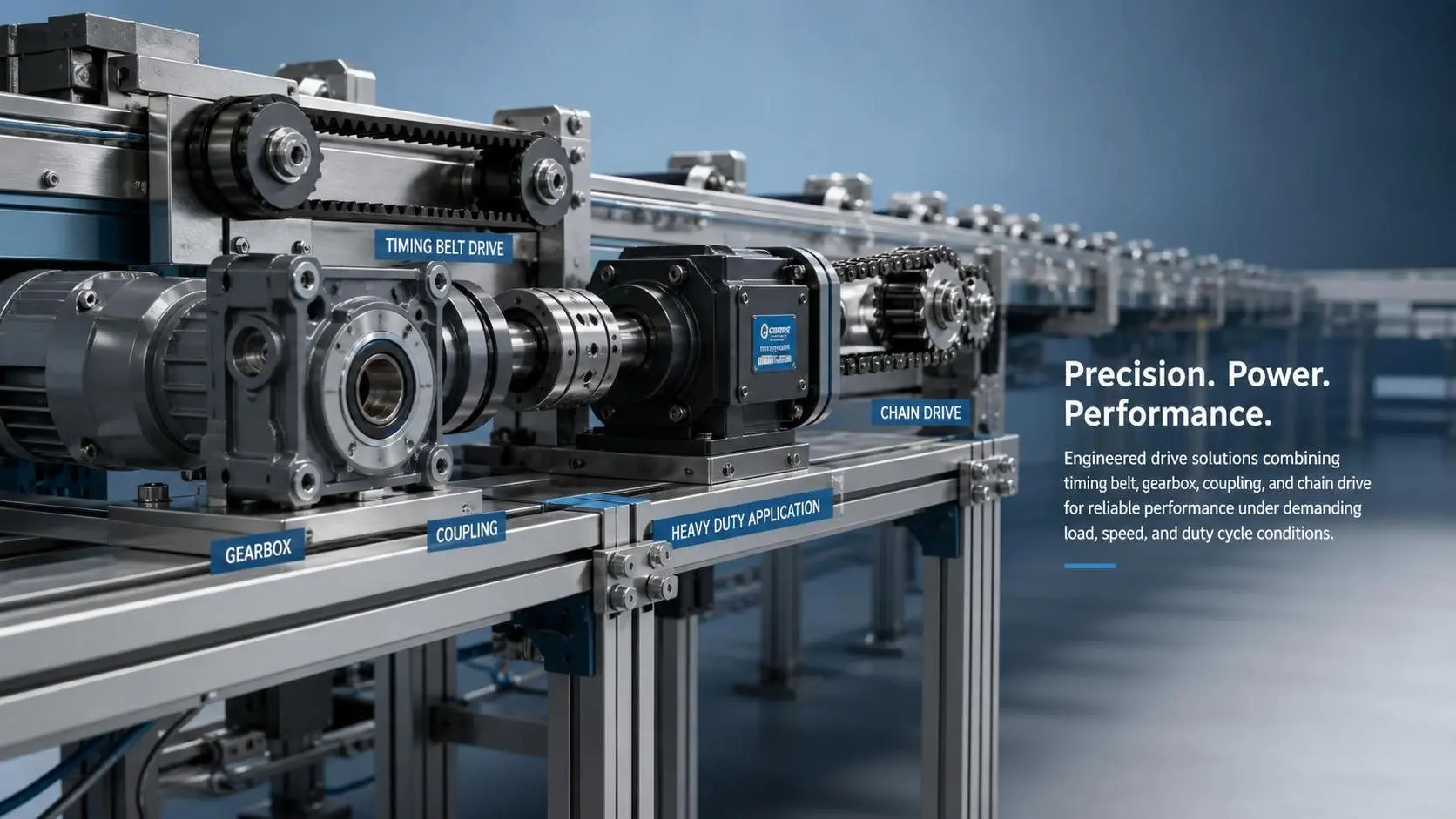
How to Select Automated Line Drive Components for Load, Speed, and Duty Cycle?
Automated line drive components selection starts with real load, speed, and duty cycle analysis. Learn how to reduce failures, improve reliability, and choose smarter for demanding production lines.
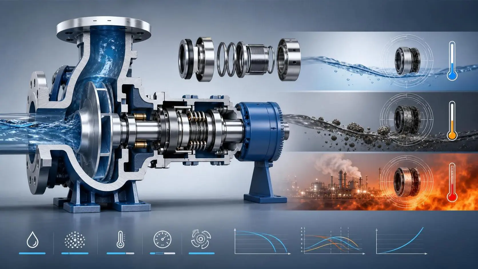
How to Choose Mechanical Seals for Industrial Applications by Fluid and Operating Conditions
Mechanical seals for industrial applications: learn how to match seal types, materials, and support systems to fluid properties, pressure, temperature, speed, and solids for longer service life.
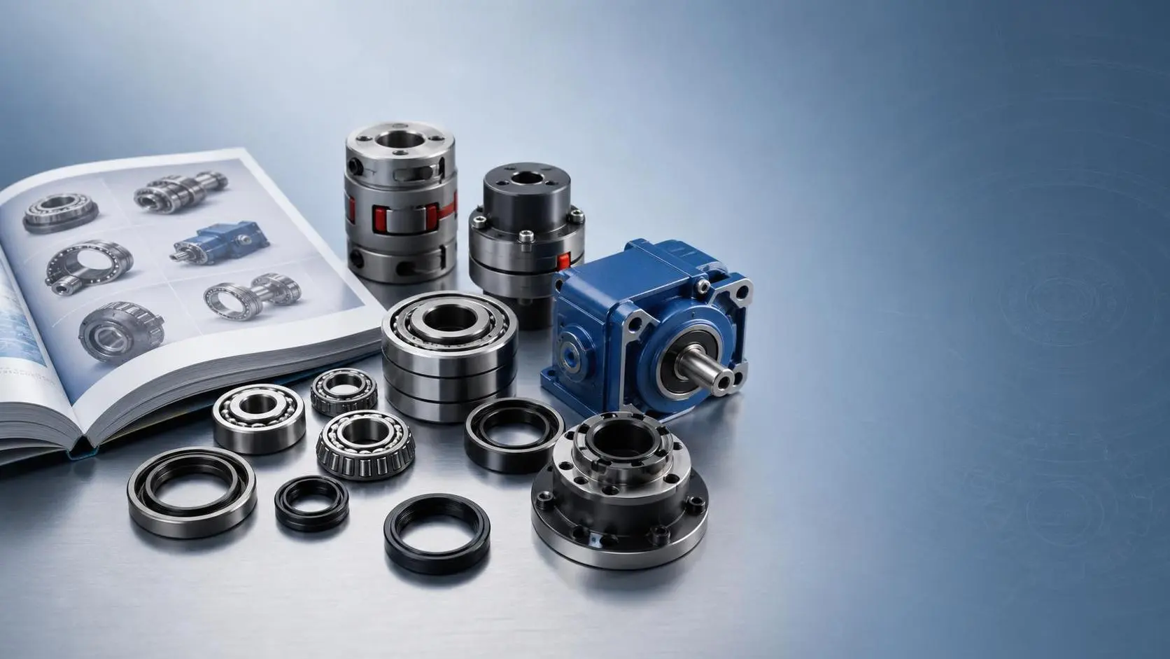
How to Use an Industrial Component Applications Catalog for Faster Part Selection
Industrial component applications catalog guide: learn how to screen parts faster, cut selection errors, and build a smarter shortlist for reliable industrial sourcing.