
Industry News
Curation by industry experts
Hot Articles
Popular Tags
Bearing Specification Resources: Finding Load Ratings and Dimensions
A bearing can look like a straightforward substitution: the bore, outside diameter, and width match, and the supplier lists a higher load rating. Yet the fit in the housing is only the beginning. Internal clearance, sealing, speed capability, and the method used to calculate loads can change whether that apparently equivalent component will survive in service.
For technical evaluators searching for industrial component specification resources for bearings, the challenge is not simply finding a table of numbers. It is finding traceable data, understanding what those numbers mean, and comparing them under the same operating assumptions. Manufacturer catalogs, standards, engineering tools, and distributor databases each have a role—but they are not equally authoritative for every decision.
Where to Find Reliable Bearing Specifications
The most useful starting point is the manufacturer’s current catalog or product page for the exact bearing designation. A full part number may identify details that a basic series number does not, including seals, shields, internal clearance, cage construction, and precision class. Download the relevant dimensional drawing and retain the catalog revision or publication date with the evaluation record.
Use other sources to fill specific gaps rather than treating all listings as interchangeable:
- Manufacturer engineering catalogs: Primary sources for published dimensions, load ratings, speed guidance, mounting recommendations, and suffix definitions.
- Manufacturer calculation tools: Useful for estimating life and checking combinations of load, speed, lubrication, and other conditions. Record the input assumptions and tool version where available.
- Standards documents: Useful for understanding standardized dimensions, tolerances, rating methods, and terminology. They do not replace the manufacturer’s data for a particular product.
- Distributor and component databases: Convenient for finding candidates and checking availability. Confirm critical values against the original manufacturer’s documentation, especially when a listing omits suffixes or units.
- Application and equipment documentation: Important for shaft and housing requirements, load cases, lubrication arrangements, and original equipment restrictions.
If sources disagree, resist averaging the values. Check whether they refer to the same variant, unit system, catalog edition, and rating definition. An older listing may describe a previous design; a distributor entry may have attached generic data to a sealed or clearance-specific part. Ask the manufacturer or authorized technical contact to resolve discrepancies that affect the decision.
Read Dimensions as an Interface, Not Just a Number
For many radial bearings, the familiar dimensions are bore diameter d, outside diameter D, and width B. These establish the basic envelope, but they do not prove that two bearings are interchangeable. An evaluator also needs to check the features that determine how the bearing seats, rotates, and transfers load into the surrounding assembly.
For tapered roller bearings and other separable designs, examine the assembled dimensions and the specific mating components, not just the envelope of an individual ring. For angular contact bearings or matched sets, arrangement, preload, and mounting orientation can also be decisive. A drawing that appears dimensionally complete may still omit the application conditions needed to establish interchangeability.
Pay close attention to units when data moves between systems. Inch and metric dimensions can be rounded in secondary listings, making a close conversion look like an exact fit. Use the original dimensional specification and its tolerances when approving a replacement.
Dynamic Load Rating: A Starting Point for Fatigue Life
The basic dynamic load rating, commonly written as C, is associated with rolling-contact fatigue life under defined conditions. It is not a general maximum operating load, and a bearing rated at a given value should not automatically be expected to run indefinitely at that load. Catalogs generally express radial ratings for radial bearings and axial ratings for thrust bearings; compare like with like.
A common basic rating life relationship is:
L10 = (C / P)p
Here, L10 is the basic rating life in millions of revolutions, C is the basic dynamic load rating, and P is the equivalent dynamic bearing load, expressed in the same force units. The exponent p is typically 3 for ball bearings and 10/3 for roller bearings. Basic rating life represents the life that 90% of a sufficiently large group of apparently identical bearings can reach or exceed under the specified conditions; it is not a guarantee for an individual bearing.
The difficult input is often P. Real machines can impose radial and axial loads together, and the equivalent load is calculated using factors appropriate to the bearing type and load ratio. Use the manufacturer’s method rather than simply adding the forces. Duty cycles, changing speeds, shock loads, and load direction may require a more detailed calculation than a single steady-state value.
ISO 281 addresses dynamic load ratings and rating life for rolling bearings. When using a catalog or software result, check which method and edition it follows. Modified life calculations may account for factors such as reliability, lubrication, contamination, and fatigue load limits, depending on the method used. They still depend on credible inputs: a precise-looking result cannot compensate for an uncertain load spectrum or unknown lubricant condition.
Static Load Rating: Check Stopped and Slow-Moving Conditions
The basic static load rating, C0, relates to a defined level of permanent deformation at the most heavily loaded rolling contact. It is especially relevant when a bearing is stationary, oscillating slowly, exposed to mounting forces, or subjected to occasional peak loads. A bearing can pass a calculated fatigue-life check and still be unsuitable for a high static or impact load.
A common screening measure is the static safety factor:
s0 = C0 / P0
P0 is the equivalent static bearing load, calculated using the appropriate bearing-specific method. The acceptable safety factor depends on the application, load uncertainty, shock severity, and requirements for smooth running and noise. Consult the manufacturer’s guidance rather than applying one universal threshold. ISO 76 covers basic static load ratings for rolling bearings; it should be read alongside the product data and application requirements.
How to Compare Bearings Across Suppliers
A side-by-side comparison is most useful when it begins with a defined application rather than a shopping list of catalog values. Establish the shaft and housing constraints, radial and axial loads, speed range, expected duty cycle, temperature, lubrication method, contamination exposure, and required service life. Identify whether the bearing locates the shaft axially or must accommodate thermal expansion.
Then compare complete part numbers and their documented attributes. The following sequence helps prevent a higher headline rating from obscuring a mismatch:
- Confirm the bearing type and arrangement. A deep-groove ball bearing, cylindrical roller bearing, and angular contact bearing do not carry combined loads in the same way, even if their principal dimensions are similar.
- Verify the full dimensional interface. Check tolerances, shoulders, chamfers, and any seal or snap-ring features against the actual assembly drawing.
- Match suffix meanings. Clearance, seals, cage materials, and other suffixes are not necessarily coded identically across manufacturers.
- Compare ratings and calculation bases. Check C, C0, units, load direction, and the applicable rating method. Do not assume a catalog value alone captures the operating duty.
- Review operating limits. Speed ratings are conditional guidance, not blanket permissions. Lubrication, seals, heat generation, fits, and load can change the permissible operating range.
- Document unresolved differences. Seek a technical review where material, cage design, mounting arrangement, or service conditions are outside the available documentation.
A practical example is a motor bearing replacement with matching d, D, and B. If the proposed bearing has a different internal clearance, an interference fit on the shaft and an elevated inner-ring temperature may leave less operating clearance than intended. Conversely, choosing a larger clearance without checking noise, vibration, and load distribution may create a different problem. The correct choice depends on the assembled and operating condition, not the unmounted clearance designation alone.
Standards Help Define the Language—Catalogs Define the Candidate
Standards provide a common framework for technical discussion. Depending on bearing type and application, relevant references may include ISO 15 for boundary dimensions of radial bearings, ISO 492 for tolerances, ISO 281 for dynamic ratings and life, and ISO 76 for static ratings. Scope matters: not every document applies to every bearing design, and national or industry-specific requirements may also be relevant. Check the current applicable edition and any equipment specification before making a compliance claim.
A standardized boundary dimension does not mean that all bearings sharing it have identical load ratings, internal geometry, materials, sealing performance, or service behavior. Manufacturers may publish different values for products with the same nominal envelope. Evaluate those values in context and confirm any critical interchangeability question with the manufacturer.
Resources such as GPT-Matrix can help evaluators follow broader developments in power transmission, tribology, materials, and maintenance practice. For an individual bearing decision, however, the traceable evidence remains the exact product documentation, the applicable standard, and a calculation tied to the actual machine duty. Keeping those sources together makes the final approval easier to review—and much less dependent on a promising number in a search result.
Recommended News

Choosing Long-Life Mining Transmissions for Heavy-Duty Haul Trucks
Long life mining transmissions start with the right duty-cycle match. Discover how to assess cooling, durability and maintenance for heavy-duty haul trucks.

How to Choose a Mechanical Reliability Consultant for Your Plant
Choose a mechanical reliability consultant with confidence. Compare technical expertise, diagnostic methods, deliverables, and proposals to find the right fit for your plant.
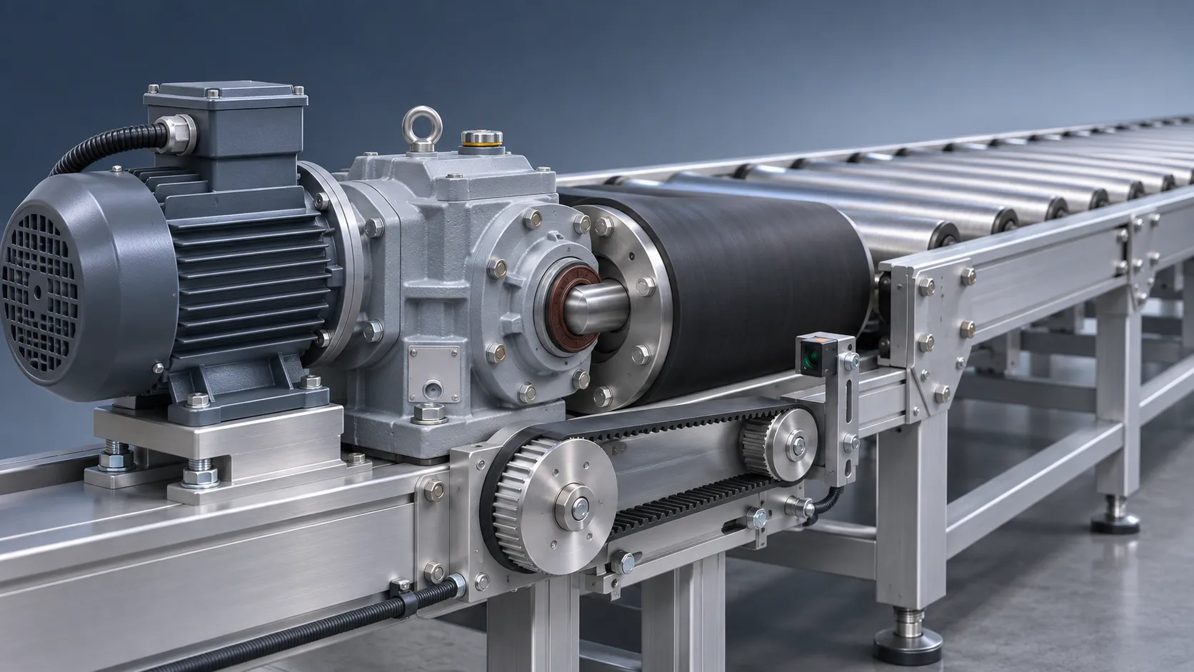
Industrial Components: Where Belts, Seals, and Gearboxes Are Used
Explore this industrial component applications overview to discover where belts, seals, and gearboxes work—and how to improve equipment reliability.

Industry 4.0 Transmission Analytics for Gearbox Condition Monitoring
Industry 4.0 transmission analytics turns gearbox data into maintenance insights. Explore sensors, fault detection and pilot strategies to make informed decisions.
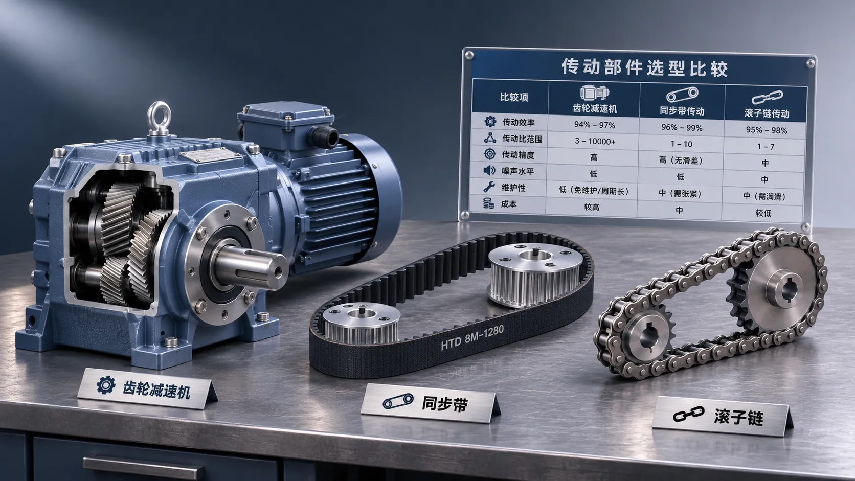
Transmission Components Price List: Comparing Quotes and Cost Factors
Compare a transmission components price list with confidence. Learn how specifications, delivery costs and supplier terms affect quotes and purchasing decisions.

Smart Transmission Components: What Drives Price and Total Cost?
Smart transmission components price is just the start. Explore the factors behind quotes and total ownership costs to compare suppliers and buy with confidence.

Choosing Long-Life Roller Chains for High-Load Applications
Discover how to choose long-life roller chains for high-load drives, from fatigue ratings and lubrication to sprocket alignment and operating costs.
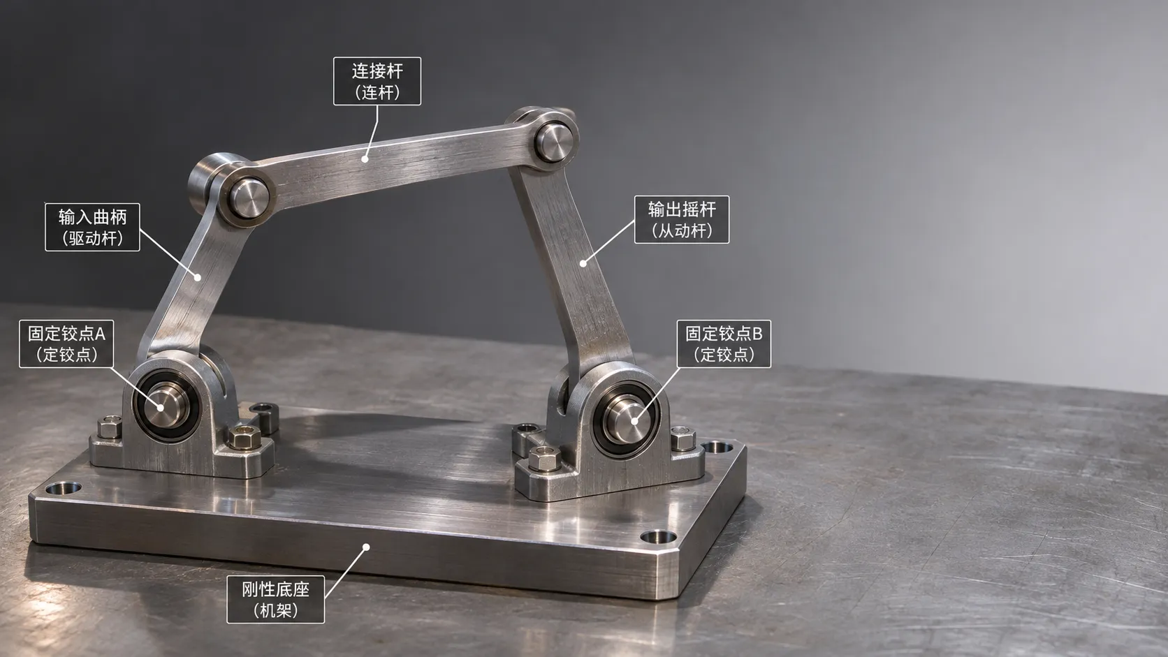
Mechanical Linkage Assemblies: How Motion and Force Are Transmitted
Explore mechanical linkage technology assemblies and learn how geometry, joints, and load affect motion, force, accuracy, and reliability.
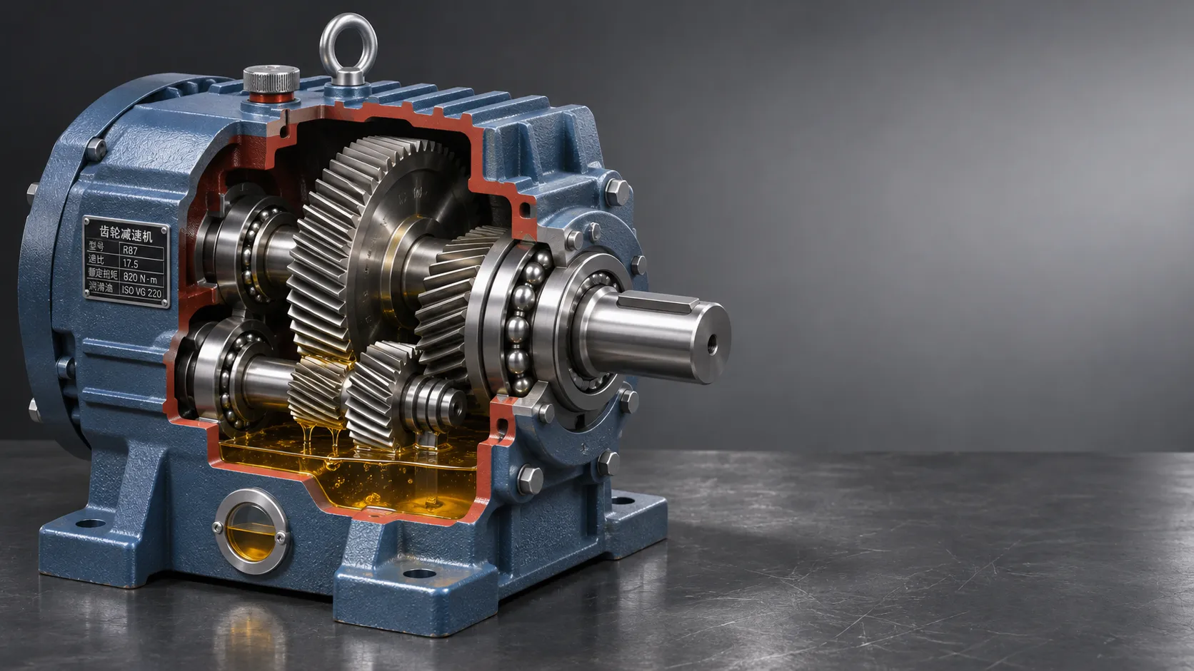
Choosing Wear-Resistant Industrial Transmissions for Long Service Life
Choose wear resistant long life transmissions with confidence. Explore load, lubrication, sealing and supplier checks to reduce downtime and service costs.