
Industry News
Curation by industry experts
Hot Articles
Popular Tags
How Can You Prevent Misalignment in Mechanical Linkages?
How Can You Prevent Misalignment in Mechanical Linkages?
Misalignment in a mechanical linkage rarely begins as an obvious failure. A conveyor may still run, a reducer may still transmit torque, and a coupling may still look intact during a walk-by inspection. Yet somewhere in the assembly, loads are no longer travelling through the intended centerlines. Bearings begin carrying edge loads, seals run hotter, flexible elements work harder than intended, and vibration gradually becomes part of normal operation.
So, how do I prevent misalignment in mechanical linkages? The practical answer is not simply “align the shafts more carefully.” Good alignment starts with design choices, continues through installation and commissioning, and depends on maintenance teams noticing small changes before they become mechanical damage. It also requires distinguishing between static alignment at installation and dynamic alignment under real load, temperature, and operating conditions.
For power transmission systems, the issue can involve shafts, couplings, chain drives, belts, gears, rod-end joints, pivots, bearings, reducers, and seals. These parts do not fail independently. A slightly soft machine base, for example, can create coupling misalignment; the resulting vibration may then shorten bearing life and eventually compromise a nearby mechanical seal. Treating each symptom in isolation is one of the costliest habits in industrial maintenance.
Misalignment Is Not One Problem
The first step is to identify what kind of misalignment is actually present. Parallel, angular, and axial displacement are the familiar categories for coupled shafts, but real installations often show a combination of all three. In a linkage with pins, bushings, and rod ends, the problem may instead be non-parallel pivot axes, side loading, worn bores, or an incorrect joint travel path.
Angular misalignment occurs when two centerlines meet at an angle rather than running parallel. Parallel, sometimes called offset, misalignment occurs when the centerlines remain parallel but do not share the same axis. Axial movement is different again: it relates to shaft end float, thermal growth, or an assembly that has been positioned too tightly between bearings. A coupling can tolerate some movement, but its allowable misalignment is not a target installation value. It is a limit, usually intended to accommodate residual error and operating movement.
This distinction matters. A flexible coupling may protect the system from minor unavoidable movement, but it cannot correct poor base preparation, distorted mounting faces, bent shafts, or a drive train that was never properly aligned. Choosing a more forgiving coupling instead of addressing the root cause often shifts stress into another component.
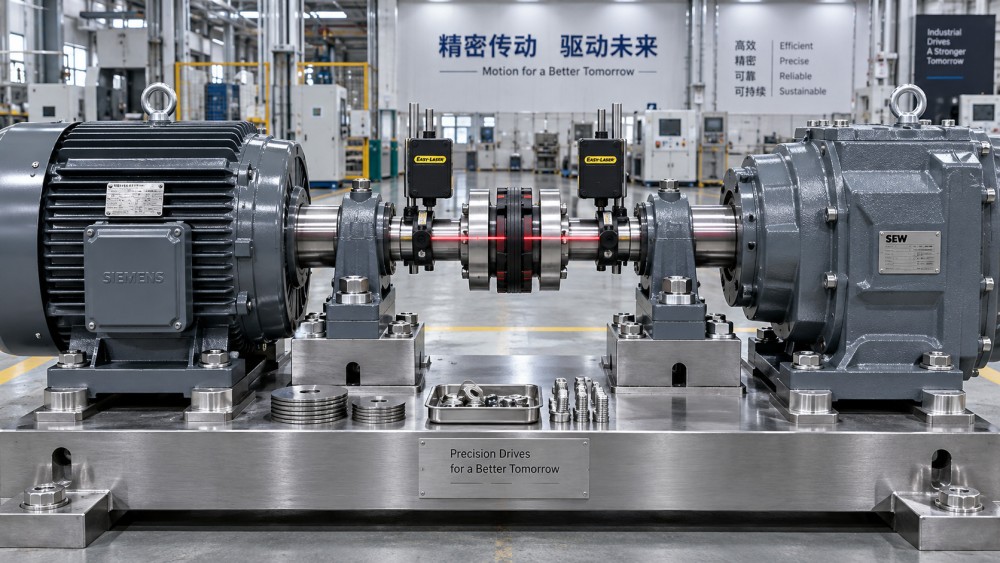
Start with a Stable Mechanical Reference
Many alignment jobs are lost before measurement begins. If the driven machine is sitting on uneven feet, the alignment reading can change as mounting bolts are tightened. This condition, commonly known as soft foot, is especially troublesome on motors, pumps, gear reducers, and packaged skids. The machine may appear level while loose, then twist slightly as the hold-down bolts pull it into contact with an irregular base.
Before aligning shafts or linkages, inspect the foundation, baseplate, mounting pads, fasteners, and shims. Surfaces should be clean and free from paint buildup, burrs, corrosion scale, oil films, or debris that can alter contact. Shims should be properly sized and installed as a controlled correction, not stacked indiscriminately until the machine happens to meet a reading. Excessive or poorly supported shimming can make later adjustments unpredictable.
For assemblies exposed to high cyclic loads, the rigidity of the supporting structure deserves as much attention as the coupling itself. A base that deflects under load can produce good cold alignment and poor operating alignment. The same applies to fabricated brackets supporting pivots or linear actuators. If a bracket flexes, the linkage geometry changes every cycle, which accelerates pin and bushing wear even when the components were installed correctly.
Design for Movement, Not Just for the Installation Drawing
A drive train does not remain in the exact position recorded during commissioning. Motors heat up, housings expand, load direction changes, and machine frames settle. Long shafts and hot-process equipment can experience meaningful thermal movement. If the alignment plan ignores that movement, a system may be cold-aligned yet run out of tolerance after reaching operating temperature.
This is where design review needs practical judgment. Engineers should determine which machine is fixed, which is allowed to move, where thrust is controlled, and whether the coupling or linkage has sufficient axial capacity. Bearing arrangements must also match the thermal behavior of the shaft. Locking both ends of a long shaft without allowing appropriate expansion can force axial loads into bearings, couplings, and seals.
Mechanical joints should also be selected according to their actual range of motion. A spherical rod end can accommodate angular movement that a rigid clevis arrangement cannot. A universal joint may be appropriate where shafts operate at an angle, but its operating behavior must be understood; joint angles and phasing affect speed variation and torsional response. In chain and belt drives, sprocket and pulley alignment is equally important. A belt that tracks against a flange or a chain that runs toward one side of a sprocket is sending an early warning.
Installation Methods: What Works, and What Often Misleads
Straightedges and feeler gauges remain useful for rough positioning, especially on accessible belt drives and simple machinery. They are quick, inexpensive, and often enough to reveal an obvious pulley offset. Their limitation is repeatability. They depend on clean reference faces, operator judgment, and the assumption that the surfaces being referenced are themselves true.
Dial indicators provide more sensitivity for shaft alignment and can be effective in experienced hands. However, indicator setups are susceptible to bracket sag, shaft runout, loose fixtures, and reading errors. Laser alignment tools can simplify measurement and calculation, particularly where machines must be adjusted in both horizontal and vertical planes. They are not magic instruments. A laser system mounted to a dirty shaft, used on a flexible base, or operated without checking soft foot will simply produce precise readings from an unstable condition.
The right comparison is therefore not “manual versus laser.” It is whether the chosen method is adequate for machine criticality, coupling type, shaft speed, accessibility, and the consequence of failure. A low-speed auxiliary conveyor and a heavily loaded reducer serving a continuous production line should not automatically receive the same alignment strategy.
Lubrication Cannot Repair Misalignment, but It Can Reveal It
Misalignment and lubrication are closely linked because misalignment changes contact conditions. In bearings, gears, chains, pins, and bushings, load is pushed toward areas not intended to carry it continuously. Lubricant films become harder to maintain, grease may be displaced from loaded zones, and local heat rises. When a joint repeatedly runs dry on one side while appearing adequately lubricated overall, its geometry should be checked.
Over-greasing is not a safe answer. Excess grease can increase churning, create heat, and obscure evidence of wear. The better approach is to use the lubricant type and interval recommended for the component and operating environment, then inspect how the lubricant behaves. Metallic debris, darkened grease, unusual leakage paths, or a persistent need for re-lubrication can indicate mechanical distress rather than a simple lubrication shortfall.
Sealing systems deserve similar scrutiny. A mechanical seal does not generally cause shaft misalignment, but seal leakage or abnormal face wear can be a downstream symptom of shaft deflection, bearing condition, or pipe strain. Replacing the seal without checking the surrounding mechanical system can lead to an expensive repeat failure.
Avoid Pipe Strain, External Loads, and “Alignment by Force”
A common commissioning mistake is aligning a pump and motor accurately, then connecting pipework that pulls the pump casing out of position. Similar problems occur when guards, hydraulic hoses, cable trays, belt tensioning devices, or poorly routed conduits place unintended loads on a machine. Alignment should be verified after relevant connections are made, not only before.
Never use coupling bolts, bearing housings, or mounting fasteners to draw misaligned parts into position. If parts only fit when forced together, the assembly is storing stress. That stress may remain hidden until the equipment reaches speed or temperature. In pivoting linkages, forcing pins through slightly offset holes can score the bore immediately and create a wear pattern that no amount of later adjustment will fully reverse.
Condition Monitoring Turns Alignment into a Maintenance Discipline
Alignment is often treated as a one-time installation task. In practice, it should be reviewed whenever a machine is moved, a motor is replaced, bearings are changed, a gearbox is rebuilt, a base is repaired, or vibration trends shift. Even a well-installed assembly can drift because of foundation settlement, bolt relaxation, corrosion, impact damage, or progressive wear in joints and bearings.
Useful warning signs include rising vibration, recurring coupling element damage, hot bearing housings, uneven belt wear, abnormal chain tracking, seal leakage, loosened fasteners, and repeated need to adjust tension. None of these proves misalignment by itself. They are prompts to inspect the system rather than replace the most visible failed component.
Condition-based maintenance can be modest or sophisticated depending on the asset. Routine visual inspections, temperature checks, and documented alignment readings may be sufficient for many machines. More critical installations may justify vibration analysis, oil condition monitoring, or permanent sensors. The key is trend information. A single vibration number is less useful than knowing whether a known machine has changed after a repair, a load increase, or a seasonal temperature shift.
Build Alignment Decisions Around the Whole Transmission System
The strongest prevention programs connect material selection, mechanical geometry, lubrication practice, installation control, and operating data. This systems view is particularly relevant as production lines become more automated and drive assemblies combine motors, reducers, synchronous belts, chains, couplings, and sealed process equipment in tighter spaces.
At GPT-Matrix, the useful question is not merely whether an individual component meets a catalogue specification. It is how the mechanical joints and power-transmission elements behave together under real operating conditions, including thermal change, load cycles, maintenance access, energy use, and supply continuity. Developments in high-performance belt materials, digitally integrated reducers, and reliability-focused sealing technologies all reinforce the same lesson: component performance depends heavily on installation and system context.
Preventing misalignment is therefore less about chasing perfect numbers on every machine and more about controlling the errors that matter for a specific drive train. Establish stable references, account for movement in service, use an alignment method suited to the machine, and investigate recurring wear as a system signal. When those habits are in place, linkages run more smoothly, maintenance becomes less reactive, and the transmission system has a far better chance of delivering the service life it was designed for.
Recommended News
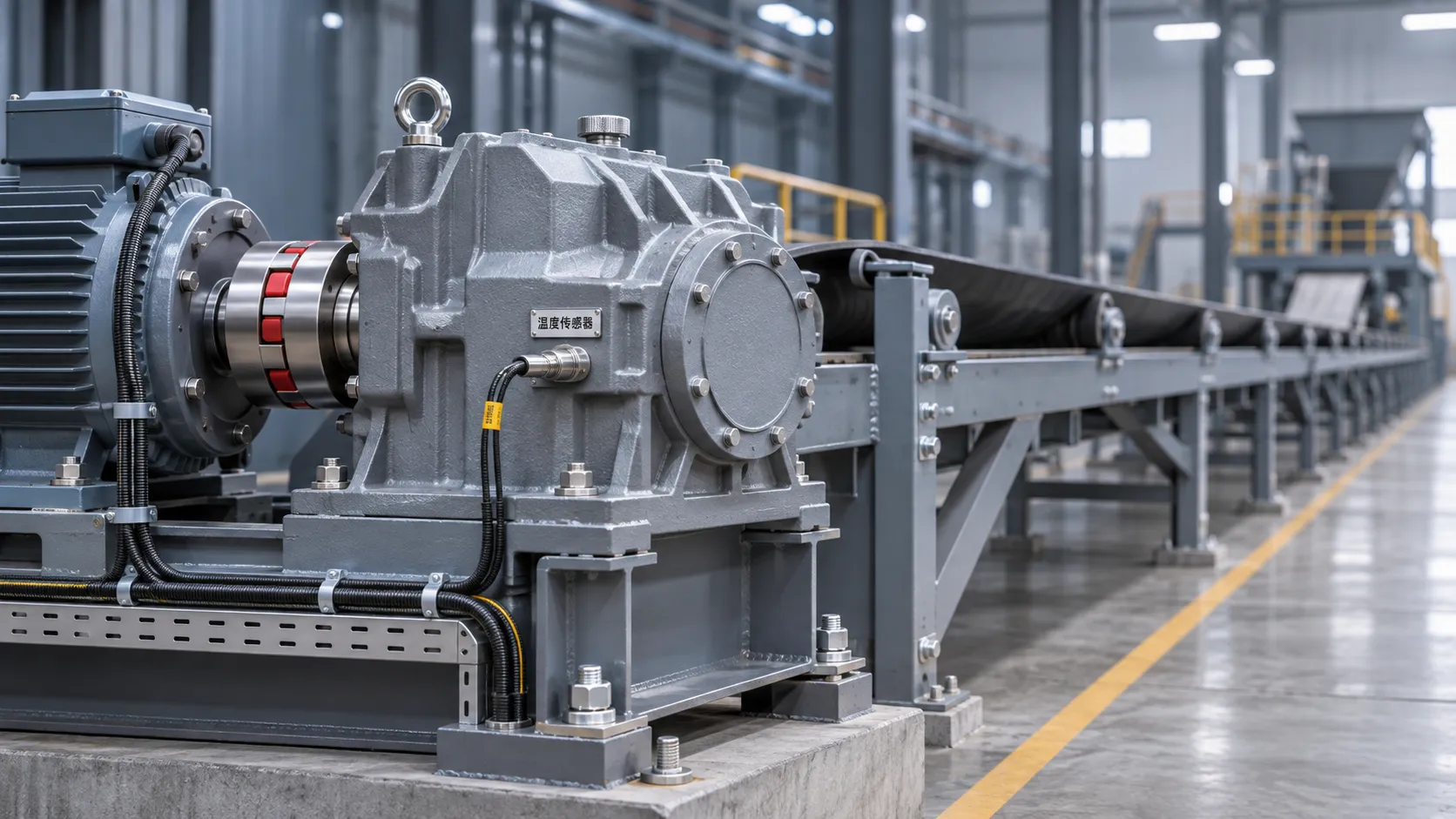
Smart Transmission Components: What Drives Price and Total Cost?
Smart transmission components price is just the start. Explore the factors behind quotes and total ownership costs to compare suppliers and buy with confidence.

Choosing Long-Life Roller Chains for High-Load Applications
Discover how to choose long-life roller chains for high-load drives, from fatigue ratings and lubrication to sprocket alignment and operating costs.
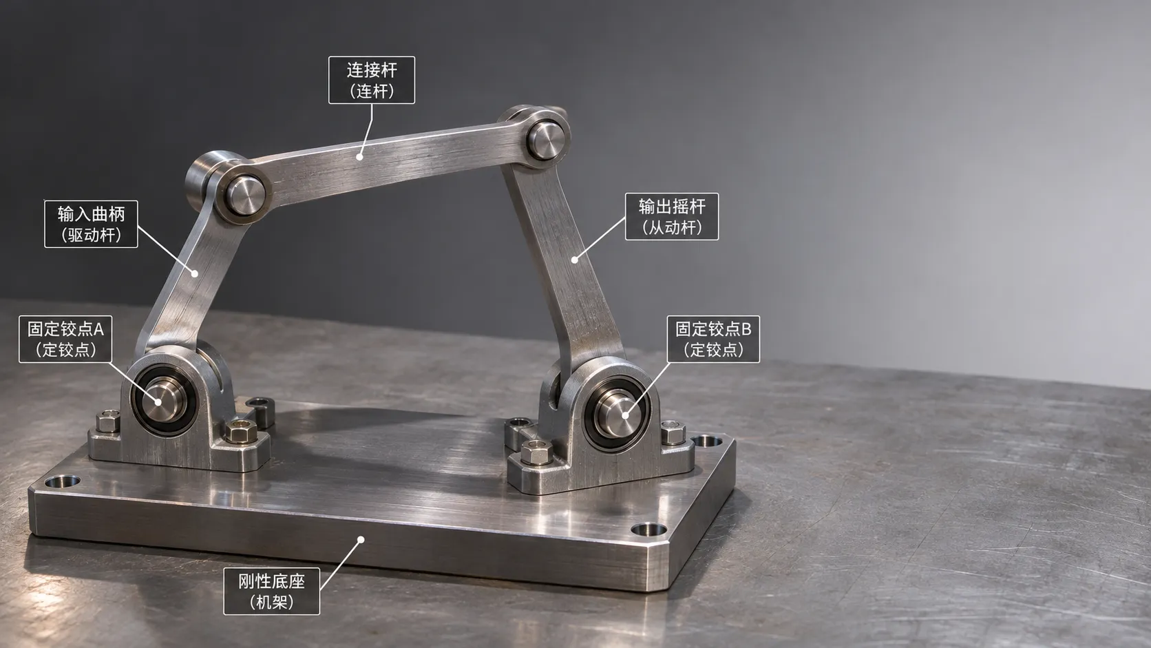
Mechanical Linkage Assemblies: How Motion and Force Are Transmitted
Explore mechanical linkage technology assemblies and learn how geometry, joints, and load affect motion, force, accuracy, and reliability.
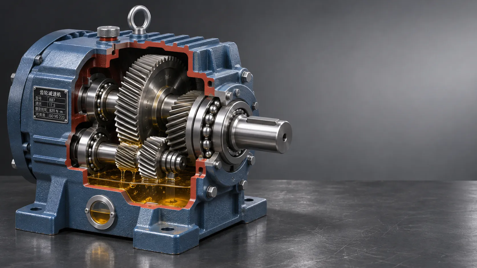
Choosing Wear-Resistant Industrial Transmissions for Long Service Life
Choose wear resistant long life transmissions with confidence. Explore load, lubrication, sealing and supplier checks to reduce downtime and service costs.
Choosing Industrial Motion Solutions for Conveyor Speed and Load Requirements
Explore industrial motion solutions for conveyor speed and load requirements. Compare drives, torque, control and duty cycles to make a confident choice.
Chain vs. Belt Drives: How to Choose for Load, Speed, and Maintenance
Explore our industrial component knowledge base for drive selection. Compare chain and belt drives by load, speed, and maintenance to find the right fit.

Choosing Heavy Equipment for Construction: Capacity, Terrain and Costs
Choose heavy duty heavy equipment with confidence. Compare capacity, terrain, productivity, and total costs to find the right machine for your construction project.
Choosing Long-Life Timing Belts: Load, Speed and Operating Conditions
Choose long-life timing belts with confidence. Compare load, speed, environment and maintenance factors to improve reliability and reduce downtime.
Green Manufacturing Technology Costs: Upfront Investment and Payback
Explore green manufacturing technology cost, from upfront investment to payback. Learn how to assess savings, manage risks, and build a stronger business case.