
Industry News
Curation by industry experts
Hot Articles
Popular Tags
Designing Reliable Mechanical Transmissions: Load, Lubrication, and Fatigue Factors
Reliability Begins with the Real Duty Cycle
Reliability in mechanical transmission design is often discussed as if it were a matter of choosing components with sufficient catalog ratings. In practice, the most consequential failures occur when rated capacity is confused with operating suitability. A gearbox may satisfy a nominal torque calculation, a belt may meet a stated power requirement, and bearings may appear to have adequate calculated life, yet the assembly can still suffer early wear, overheating, vibration, or unexpected downtime.
For technical evaluators, the central question is not whether a transmission component can operate under ideal conditions. It is whether the complete system can sustain its actual duty cycle with an acceptable probability of failure, a manageable maintenance burden, and predictable degradation. That requires examining the interaction among load spectrum, lubrication regime, alignment, environmental exposure, material fatigue, and the consequences of operating variation.
This distinction matters across automated production lines, bulk-material handling, mobile equipment, pumps, compressors, machine tools, and process plants. In many of these applications, the transmission is not the visible source of value, but it determines whether the wider asset can achieve its planned availability. A low-cost coupling, seal, bearing, or reducer can become a high-cost decision when its failure stops a production cell, contaminates a process, or damages an upstream motor and downstream driven equipment.
Rated Load Is a Starting Point, Not a Design Conclusion
Mechanical transmission systems experience more than steady torque. They see starts and stops, reversals, shock events, inertia-driven peaks, torsional oscillations, thermal expansion, and sometimes operator-induced overloads. A component selected only against average power can therefore be acceptable on paper while being structurally or tribologically unsuitable in service.
Technical assessment should begin by separating the load into several categories:
- Continuous operating load: the torque, speed, and power applied during normal production.
- Transient load: acceleration, deceleration, startup, emergency stopping, load engagement, and directional reversal.
- Peak or shock load: jams, impact loading, process upsets, material surges, and external disturbances.
- Off-design load: operation at low speed, excessive temperature, intermittent duty, reduced lubrication, or abnormal alignment.
The load spectrum is more useful than a single maximum value because fatigue damage is cumulative. Thousands of moderate cycles can be more damaging than an occasional high-load event, depending on geometry, material condition, lubrication film thickness, and local stress concentration. Conversely, a drive that spends most of its time lightly loaded may still require protection against rare peaks that exceed tooth-root strength, belt tensile capacity, coupling torque limits, or bearing static load capability.
A practical evaluation should identify the torque-versus-time profile, the number of starts per hour, the expected reversal frequency, and the inertia of both the driver and driven mass. This is especially important where variable-frequency drives are used. Motor control can reduce mechanical shock in some cases, but rapid ramp profiles, torque boosting, regenerative braking, and low-speed high-torque operation can introduce different stresses into gear meshes, shafts, couplings, and bearings.
Service factors are useful only when their assumptions match the application. A generic multiplier may account for broad categories such as moderate shock or heavy duty, but it does not replace measured or credibly estimated process data. Where downtime has a high cost, evaluators should ask whether the supplier’s rating already includes a service factor, what duty class was assumed, and whether the calculation is based on thermal capacity, fatigue capacity, or both. These limits can differ substantially.
Torque Capacity Can Be Limited by Heat
Gear reducers illustrate the difference between mechanical and thermal rating. A reducer may have sufficient gear and shaft strength for the transmitted torque but still be unable to reject the heat generated by mesh losses, churning, bearings, seals, and lubrication. Ambient temperature, enclosure design, oil viscosity, mounting orientation, fan performance, and operating speed all affect thermal balance.
For long-duration operation, especially at elevated ambient temperatures or in enclosed installations, thermal capacity deserves the same attention as tooth strength. Excessive oil temperature accelerates lubricant oxidation, reduces viscosity, weakens the elastomeric properties of seals, and can shorten bearing life. It also changes the load-carrying lubrication film in gears and rolling contacts. A drive that survives a short acceptance test may therefore degrade rapidly in continuous production.
Lubrication Is a Reliability System, Not a Maintenance Detail
Lubrication failures are often described as maintenance failures, but many begin as design or specification failures. The lubricant grade may be unsuitable for the temperature range, the oil volume may be inadequate for the mounting position, relubrication access may be impractical, or the sealing arrangement may not match the contamination environment. In these cases, asking maintenance teams to “lubricate correctly” does not solve the underlying engineering mismatch.
The objective of lubrication is not simply to make components move smoothly. It is to establish and maintain a protective film between surfaces, remove or distribute heat, manage wear particles, limit corrosion, and support seal performance. The appropriate lubricant depends on rolling or sliding contact conditions, speed, load, temperature, material pairing, and exposure to water, dust, chemicals, or product contamination.
Gear contacts, rolling-element bearings, chains, and mechanical seals do not operate under identical lubrication regimes. A lubricant that provides adequate viscosity for a heavily loaded slow-speed gearbox may generate excessive churning losses in a high-speed unit. Grease selected for water resistance may not offer the required low-temperature pumpability. An oil with additives appropriate for certain gear contacts may need further compatibility review where yellow metals, coatings, elastomers, or food-contact requirements are involved.
Viscosity selection should be tied to operating temperature rather than room-temperature handling characteristics. The oil film that protects metal surfaces becomes thinner as temperature rises. At the same time, excessively high viscosity can increase drag, raise operating temperature, and impair circulation. The result is a design tradeoff: enough viscosity to support the contact load, but not so much that the lubricant itself becomes a major source of heat and loss.
In critical systems, oil analysis can turn lubrication from a reactive task into an operating indicator. Trends in viscosity, oxidation, water content, particle count, and wear debris may reveal abnormal conditions before a catastrophic failure. However, the value of oil analysis depends on consistent sampling points, intervals, and interpretation. A single contaminated sample should not automatically trigger expensive component replacement; it should trigger confirmation, inspection of filtration and seals, and comparison with the asset’s operating history.
Contamination Changes the Component Life Model
Laboratory life calculations commonly assume clean lubrication and controlled installation. Industrial environments rarely meet those assumptions. Fine dust, moisture ingress, washdown fluids, metal debris, process chemicals, and degraded seal material can alter the expected life of bearings and gears dramatically. In dusty bulk handling, mining, cement, agricultural, and outdoor installations, contamination exclusion may be more decisive than a modest increase in nominal bearing capacity.
This changes specification priorities. The evaluator should consider labyrinth arrangements, contact seals, breathers, filtration, grease purge paths, shaft surface finish, seal lip material, housing protection, and maintenance accessibility as one system. More sealing is not automatically better: contact seals add friction and heat, and poorly selected seals can fail under shaft runout, pressure fluctuation, or thermal cycling. The appropriate solution is the one that controls contaminant ingress without creating an unacceptable thermal or frictional penalty.
Fatigue Is Driven by Local Stress and Repetition
Fatigue is the long-term mechanism behind many failures that initially appear sudden. Gear teeth crack at the root, rolling elements develop spalling, shafts fail near shoulders or keyways, belts lose tensile cords, and couplings fracture around bolt holes or flexible elements. The visible final break is only the last stage of a damage process that may have developed over months or years.
In transmission design, fatigue risk depends on stress amplitude, mean stress, cycle count, surface condition, residual stress, heat treatment, material cleanliness, geometry, and environmental effects. A shaft with sufficient static strength may still have poor fatigue life if a sharp shoulder, keyway, spline transition, or corrosion pit concentrates stress. A gear with an appropriate nominal module may still suffer pitting if its contact stress, lubrication film, and surface finish are not suitable for the intended duty.
Technical evaluators should be cautious when design discussions rely on a single “safety factor.” Safety factors remain necessary, but they cannot represent every failure mechanism equally well. A safety factor against yielding does not establish fatigue resistance. A bearing life calculation does not address electrical erosion, lubricant starvation, or cage instability. A belt tensile rating does not fully describe performance under pulley misalignment, heat exposure, repeated bending, or chemical attack.
Surface engineering also deserves attention. Carburizing, nitriding, induction hardening, grinding quality, shot peening, and coatings can each improve performance when applied correctly. They can also introduce risk if process control is weak. Case depth, hardness gradients, grinding burn, distortion, and residual stress should be understood for components carrying high cyclic loads. For critical applications, material certificates and process traceability may be more meaningful than broad claims about “high-strength alloy steel.”
Alignment Is Not an Installation Footnote
Misalignment is one of the most common sources of preventable transmission distress. It creates additional bearing loads, uneven gear contact, coupling heating, seal wear, belt tracking problems, and vibration. Yet alignment is frequently checked only during initial installation, even though machine position changes as foundations settle, structures deflect, temperatures rise, and connected equipment is modified.
Cold alignment targets should account for expected thermal growth. A motor and driven machine that are perfectly aligned while cold may be significantly offset at operating temperature. The relevant question is therefore whether the shafts achieve acceptable alignment under stable operating conditions. In sensitive installations, laser alignment and thermal growth assessment are justified, but they should be paired with checks of base flatness, soft foot, pipe strain, coupling condition, and machine movement. Precision measurements cannot compensate for a structurally unstable mounting arrangement.
Flexible couplings should not be treated as permission to ignore alignment. Their purpose is to accommodate a defined amount of unavoidable movement while transmitting torque and managing torsional behavior. Selecting a more flexible coupling may reduce some load transfer, but it can also introduce torsional compliance, backlash, heat generation, or fatigue concerns. The coupling must be evaluated as part of the shafting system, particularly where servo motion, reciprocating loads, or high-inertia starts are present.
Evaluate the Full Transmission Path
A reliable design is rarely created by optimizing each component independently. The motor, variable-frequency drive, coupling, gearbox, shafts, bearings, belts or chains, seals, driven machine, foundation, and control strategy form a connected system. Changes in one element can shift the failure mode elsewhere.
For example, increasing gearbox ratio may reduce motor-side torque but increase reflected inertia and change acceleration performance. Raising belt tension may reduce slip while increasing radial load on bearings. Selecting a stiffer coupling may improve positional accuracy while transmitting more torsional vibration. Upgrading to a higher-capacity bearing may not improve life if housing stiffness, lubrication cleanliness, or shaft tolerance remains inadequate.
This is why root-cause reviews should not stop at the failed part. Replacing a damaged bearing without examining alignment, fit, lubrication, electrical grounding, vibration, and loading often leads to repeat failure. The same applies to gearboxes that repeatedly overheat, belts that require frequent tension adjustment, or seals that leak after apparently correct replacement.
Questions That Improve a Technical Evaluation
Before approving a transmission design, procurement specification, or retrofit, evaluators should be able to answer several practical questions:
- What is the verified load spectrum, including startup, stopping, jamming, and reversal events?
- Which component limit governs the design: strength, fatigue, thermal capacity, speed, deflection, or lubrication film?
- What ambient temperature, contamination, washdown, humidity, and chemical exposure will occur in service?
- How will alignment be established and rechecked after thermal stabilization and normal operation?
- What lubrication method, interval, cleanliness target, and sampling approach are feasible at the installation point?
- What happens when an abnormal load occurs: does the system slip, trip, shear, overload safely, or transfer damage into a more expensive component?
- What evidence supports the claimed life: recognized calculation methods, test data, field history in similar duty, or only nominal catalog ratings?
Standards and supplier calculations are important tools, but their applicability must be reviewed. ISO, AGMA, IEC, DIN, and manufacturer-specific methodologies may use different assumptions, duty classifications, life definitions, and allowable stress approaches. Where compliance with a particular standard is required, the exact edition, scope, and calculation inputs should be confirmed rather than inferred. Requirements tied to hazardous areas, food processing, functional safety, pressure containment, or sector-specific machinery rules may add separate constraints that are outside a conventional mechanical rating calculation.
Reliability Is Increasingly a Data Quality Issue
Condition monitoring, connected drives, online oil sensors, vibration analysis, and thermal imaging are changing how industrial teams manage transmission reliability. Their value is not that they eliminate failure; their value is that they reveal deterioration early enough to make a controlled decision. A temperature trend can expose lubricant loss or rising friction. Vibration data can identify mesh defects, imbalance, looseness, or bearing damage. Motor current signatures may indicate loading changes in connected mechanical equipment.
But monitoring is only as useful as the operating context attached to it. A high vibration reading without speed, load, process condition, and maintenance history may lead to false alarms or missed deterioration. The most productive programs combine baseline measurements, repeatable routes or online sensing, clear alarm logic, and an escalation path that links technical evidence to maintenance action.
For organizations building global sourcing or lifecycle strategies, reliability data also affects supplier evaluation. Delivery performance and purchase price remain relevant, but they do not show whether a component will maintain geometry, lubrication performance, and material integrity across the planned service interval. Supplier assessment should include documentation discipline, process capability, traceability for critical materials, repair support, spare-parts continuity, and the ability to explain design limits in application-specific terms.
The strongest transmission designs are not necessarily those with the largest nominal ratings or the most sophisticated monitoring package. They are the designs in which the load case is understood, lubrication can be maintained, fatigue-sensitive details are controlled, and abnormal operating conditions have been considered before the system reaches the field. For technical evaluators, that is the useful threshold: not simply asking whether the drive will run, but whether it will continue to run predictably when real industrial conditions begin to challenge it.
Recommended News
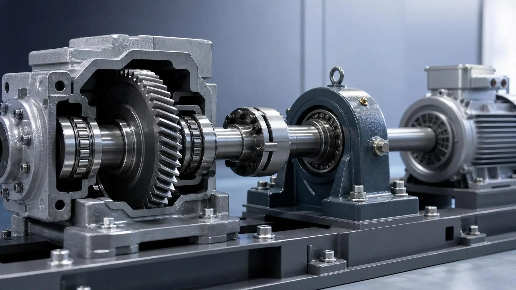
How to Define Load Requirements in Component Specifications for Safe Selection
Component specification guidance for load requirements: define load paths, duty cycles, peaks, environmental limits, and safety margins for safer component selection.
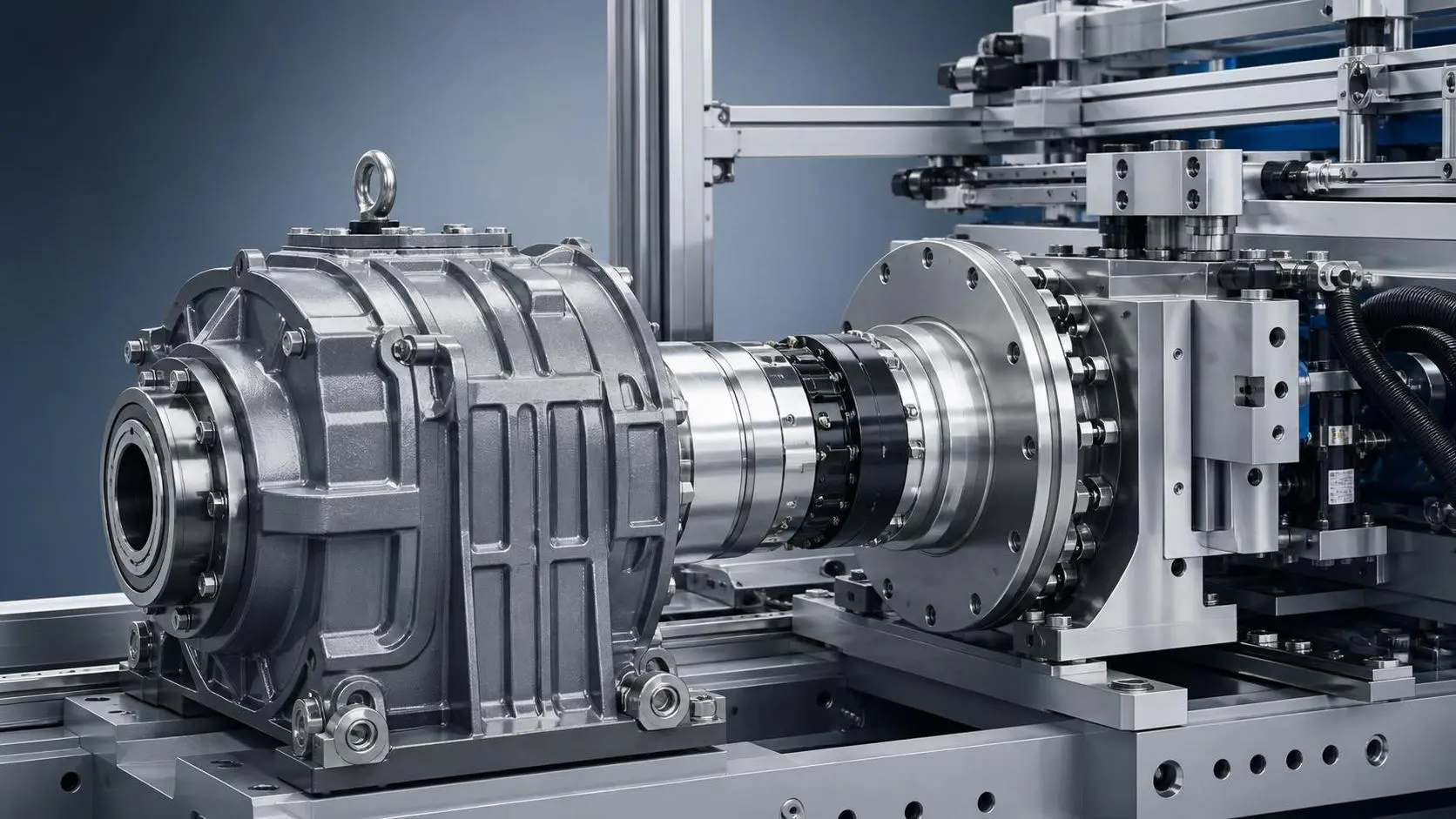
How to Evaluate Precision Engineered Transmissions for High-Load Industrial Systems
Precision engineered transmissions for high-load systems: learn how to assess load profiles, thermal limits, sealing, stiffness, and lifecycle reliability for smarter industrial decisions.
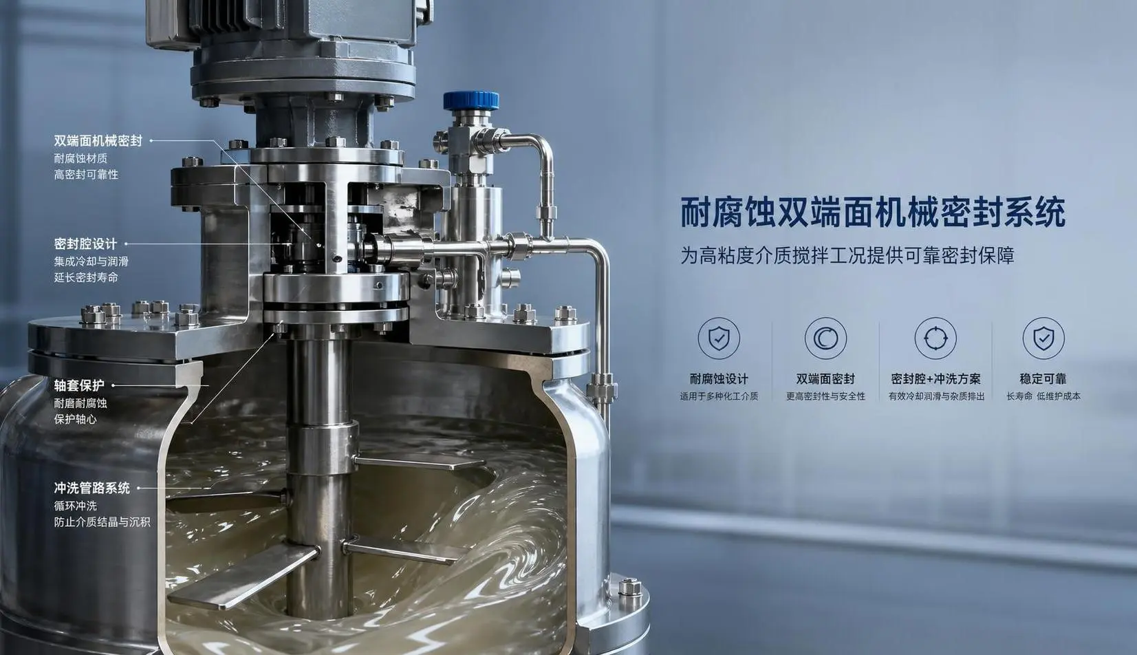
How to Select Mechanical Seals for Mixers in Corrosive or High-Viscosity Processes
Mechanical seals for mixers in corrosive or high-viscosity processes require the right materials, design, and support system. Learn how to choose a reliable seal and reduce leaks, downtime, and maintenance.
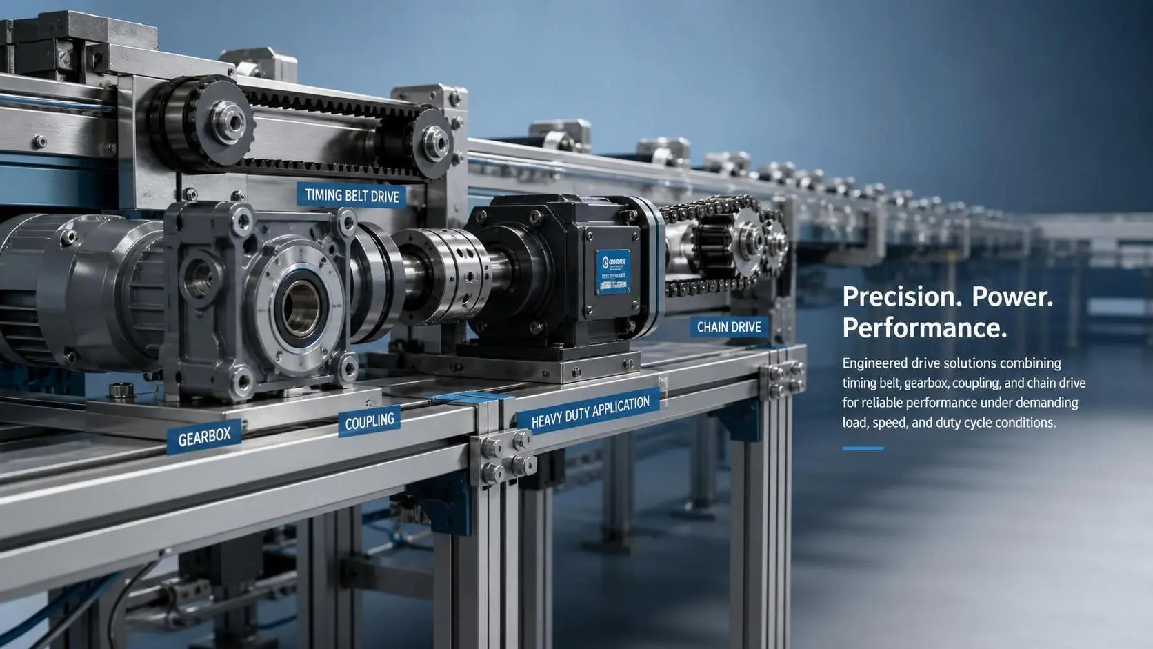
How to Select Automated Line Drive Components for Load, Speed, and Duty Cycle?
Automated line drive components selection starts with real load, speed, and duty cycle analysis. Learn how to reduce failures, improve reliability, and choose smarter for demanding production lines.
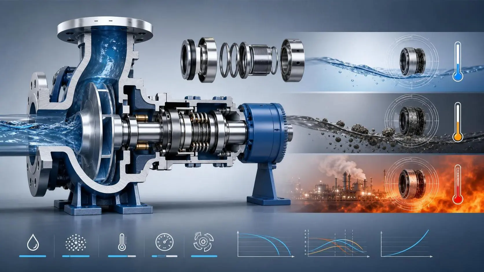
How to Choose Mechanical Seals for Industrial Applications by Fluid and Operating Conditions
Mechanical seals for industrial applications: learn how to match seal types, materials, and support systems to fluid properties, pressure, temperature, speed, and solids for longer service life.
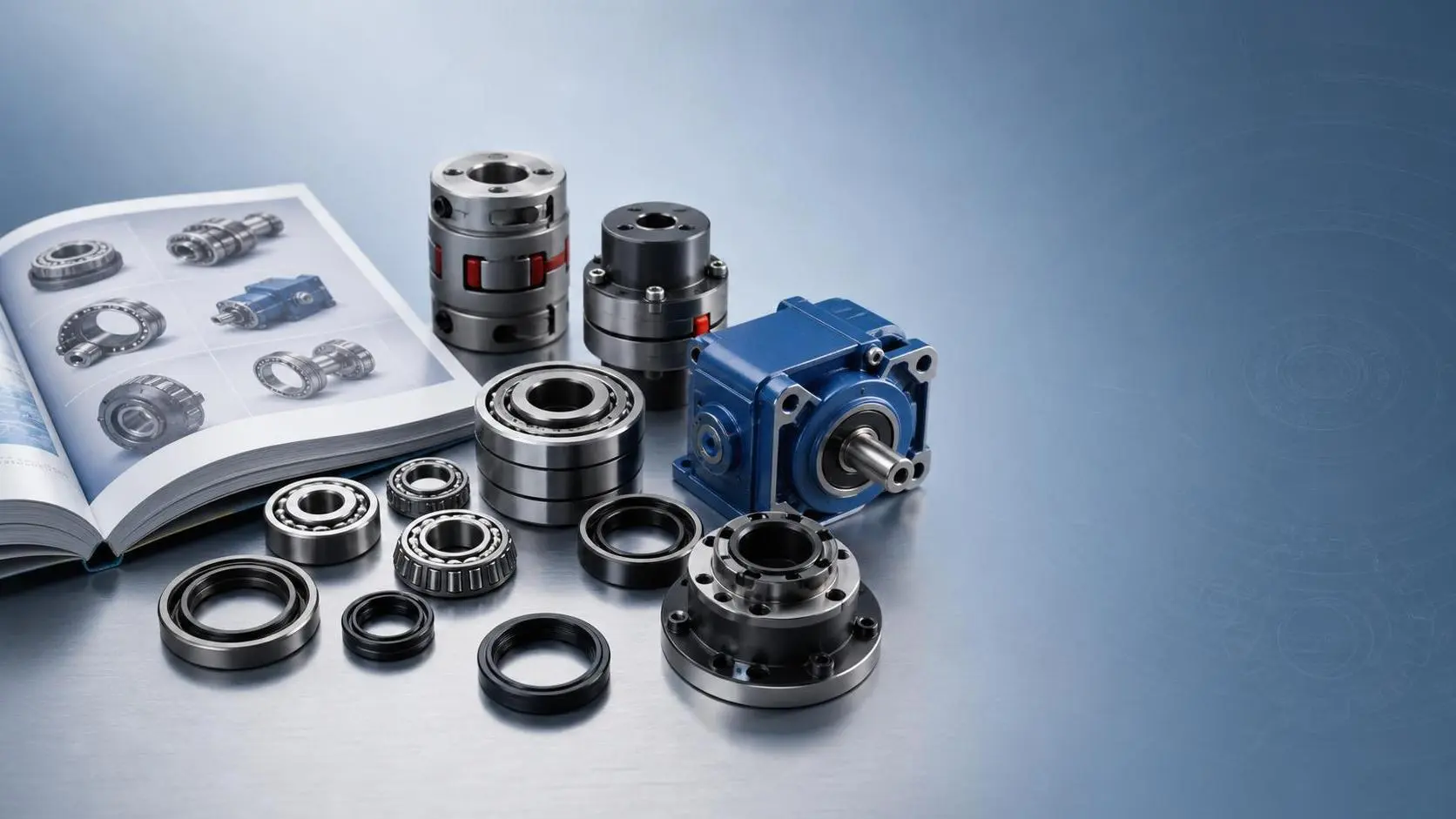
How to Use an Industrial Component Applications Catalog for Faster Part Selection
Industrial component applications catalog guide: learn how to screen parts faster, cut selection errors, and build a smarter shortlist for reliable industrial sourcing.

When Does a Mechanical Efficiency Optimization Service Deliver Real ROI?
Mechanical efficiency optimization service ROI becomes real when it cuts energy waste, downtime, and maintenance costs in critical assets. Learn when optimization truly pays off.
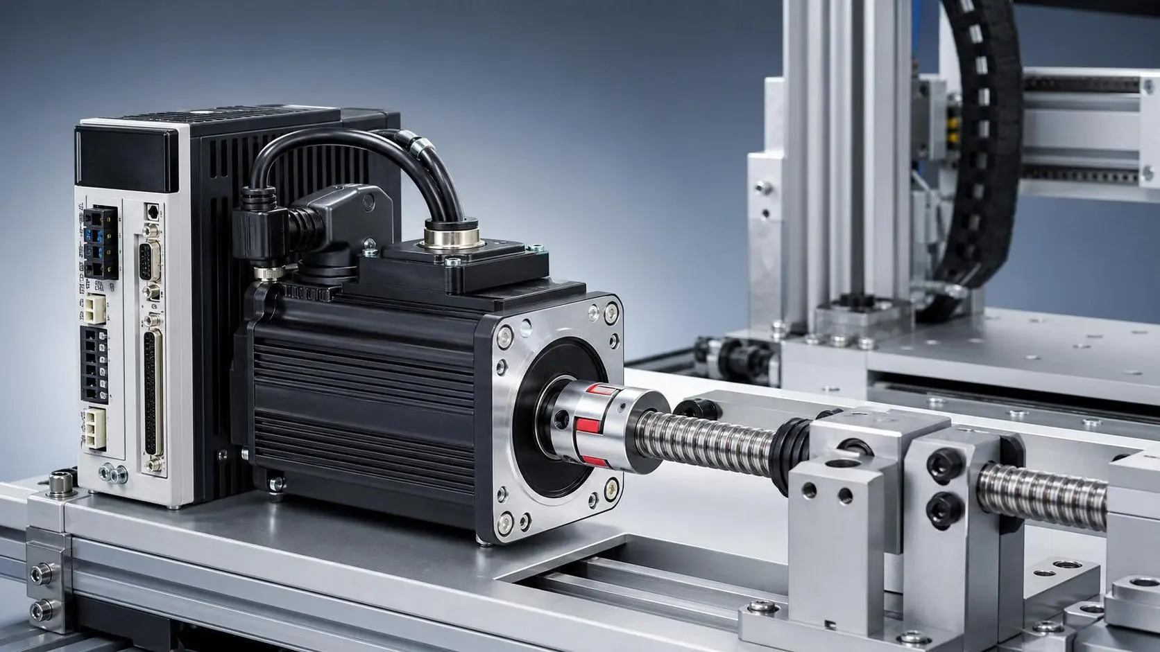
How to Read Servo Motor Specifications for Industrial Component Selection
Industrial component specification resources for servo motors: learn how to read torque, speed, inertia, and thermal data to choose the right motor with less risk and cost.

How to Evaluate Industrial Motion Control Solutions for Semiconductor Tools?
Industrial motion control solutions for semiconductor tools: learn how to compare precision, contamination control, thermal stability, and integration risk for smarter selection.