
Industry News
Curation by industry experts
Hot Articles
Popular Tags
Preventing Heavy-Equipment Transmission Failures Caused by Repeated Shock Loads
Shock Loads Are a Transmission-Life Problem, Not Just an Operator-Handling Problem
Repeated shock loading can shorten the life of heavy equipment transmissions long before a visible failure occurs. A machine may continue to travel, lift, push, or rotate normally after a hard impact, an abrupt direction change, or a sudden load pickup. Yet every event can add small amounts of damage at gear teeth, bearing raceways, splines, shafts, couplings, and mounting interfaces. Over time, that accumulated damage turns into backlash, noise, elevated temperature, oil contamination, tooth breakage, or a failure that appears to happen without warning.
For aftermarket maintenance teams, the practical question is rarely whether shock loads exist. Excavators hitting rock, wheel loaders entering piles, crushers taking uneven feed, haul trucks operating on poor haul roads, and attachments reaching mechanical stops all generate them. The maintenance decision is whether the transmission system is absorbing those loads within its intended capacity, or whether impact energy is bypassing the designed load path and concentrating at a weakened component.
The most effective response combines three actions: identify where shocks enter the driveline, inspect the components that show damage first, and correct the operating or installation condition that keeps recreating the event. Replacing a damaged gearbox or coupling without addressing the source of the shock often restarts the same failure sequence.
Why Repeated Impacts Cause Different Damage Than Steady High Load
A transmission can operate reliably under a high but relatively stable torque load and still fail under lower average torque if that torque arrives as repeated impacts. Steady load gives lubricants, shafts, gears, and bearings a more predictable duty cycle. Shock loading creates rapid torque reversals and transient peak forces that may exceed the nominal working load by a wide margin.
Those short-duration peaks matter because they can momentarily reduce the oil film separating gear teeth and bearing elements. Once contact moves toward boundary lubrication, surface distress can begin. The visible result may be scuffing, micropitting, brinelling, or spalling, depending on the component, lubricant condition, material, and load direction. A single severe event can crack a tooth root or deform a spline. More commonly, moderate impacts create small defects that grow through fatigue.
Shock loads also expose looseness. A worn universal joint, deteriorated engine mount, loose gearbox support, excessive coupling clearance, or worn axle spline may be tolerated during smooth operation. Under impact, the clearance becomes travel distance. The component accelerates across that gap and strikes the mating surface, increasing localized stress and creating a hammering cycle. This is why replacing only the visibly failed part can produce a repeat failure soon afterward.
Typical points where shock energy enters the system
- Rapid forward-reverse shifts or aggressive directional changes before machine speed has decayed.
- Bucket, blade, breaker, grapple, or other attachment contact with hard material or a mechanical stop.
- Sudden traction changes, including wheel spin followed by grip, track slip, or one wheel dropping into a rut.
- Uneven crusher feed, blocked conveyors, jammed driven equipment, or abrupt release of stored material.
- Overspeed descent, harsh braking, or a driven load that back-drives the transmission.
- Misalignment or loose supports that allow the driveline to move during torque reversal.
These events do not all damage the same components. A harsh directional shift may first affect clutch packs, torque converter elements, splines, and planetary gears. Repeated attachment impact may travel through a power take-off, pump drive, reduction gearbox, or final drive. Maintenance teams should map the load path for the machine and attachment combination in front of them rather than applying a generic gearbox inspection routine.
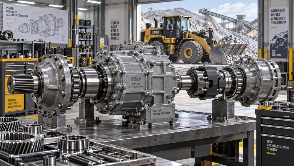
Look for the Failure Pattern Before Ordering Parts
Transmission damage caused by repeated shock loads tends to leave a pattern. The pattern is more valuable than a single broken component because it points toward the initiating condition. A chipped gear tooth can result from overload, but the adjacent wear marks, bearing condition, oil debris, shaft fit, and machine history help distinguish one severe event from recurring impact.
Start with the machine’s recent operating behavior. Ask whether the issue followed a specific impact, attachment change, road condition, operator change, recovery event, or repair. A failure after an isolated overload may call for a focused repair and a check of protective devices. A machine that repeatedly experiences harsh engagement or cyclic impact needs a broader review of controls, mounting, alignment, hydraulic settings, and driveline clearances.
Inspection findings that often point to repeated shock loading
Where a table format is not practical during field work, the same logic can be applied in sequence: inspect the failed component, then inspect the part that drives it, then the support system that holds both in position. For example, a damaged reduction gearbox should prompt checks of coupling condition, motor or engine mounting, attachment inertia, and the controls that command engagement. The gearbox is often the point where the damage becomes visible, not necessarily where the shock began.
Oil inspection deserves more weight in this type of diagnosis. A drain plug covered with coarse ferrous fragments signals a different urgency than a light, fine metallic paste. Cutting open the filter and separating magnetic from non-magnetic debris can help narrow the likely source. The maintenance record should note particle type and approximate quantity before flushing or disassembly, because that evidence can be lost quickly once corrective work starts.
Control Clearance, Alignment, and Engagement Quality
Many shock-load failures are aggravated by conditions that appear minor during routine service. Excessive backlash, loose mounting bolts, compressed or cracked isolators, worn driveline joints, and poor shaft alignment change the way impact energy moves through heavy equipment transmissions. Instead of sharing the load across gear teeth and bearing surfaces as intended, the assembly strikes, twists, or deflects before it carries torque.
Clearance must be evaluated against the machine manufacturer’s limits, not against a visual impression that a part is “still usable.” In a heavily loaded driveline, even modest movement can become destructive when direction reverses several times per shift. Pay particular attention to interfaces where torque changes direction: couplings, splined shafts, planetary carriers, axle inputs, PTO drives, and reduction-stage connections.
Alignment should also be assessed under realistic support conditions. A coupling aligned with the machine unloaded may run out of alignment when the boom is extended, the body is loaded, the frame articulates, or the attachment applies reaction force. Inspecting mount deflection, not just static alignment readings, is often necessary where failures recur after apparently correct installation.
Engagement quality is another common source of avoidable impact. Abrupt clutch application, delayed hydraulic response followed by a hard engagement, incorrect pressure settings, sticking control valves, or electronic calibration problems can impose torsional shocks that are not obvious from outside the machine. Where the transmission uses hydraulic clutch packs or electronically controlled shifts, maintenance teams should include fluid condition, pressure stability, solenoid response, and calibration status in the investigation. Mechanical wear and control faults frequently coexist: a harsh shift damages components, and the resulting debris or heat makes the shift problem worse.
Use a Maintenance Routine Built Around Events, Not Only Hours
Hour-based maintenance remains necessary for oil, filters, and scheduled inspections, but shock exposure does not follow a clean hourly pattern. A machine may operate gently for hundreds of hours and then experience enough severe impacts in one shift to justify an earlier inspection. Maintenance planning improves when high-shock events are treated as inspection triggers.
Examples include a driveline seizure, attachment strike, severe wheel spin and regain of traction, abrupt stop under load, collision, major hydraulic overpressure event, or recovery operation involving towing or pushing beyond normal duty. The response does not always require teardown. It should, however, establish a documented baseline through oil checks, temperature observations, noise assessment, mounting inspection, and functional testing before the machine returns to demanding work.
A practical post-event inspection can include:
- Checking for new leakage, loose fasteners, shifted mounts, damaged guards, and distorted driveline supports.
- Listening for changed gear whine, knocking during direction changes, or delayed engagement under controlled operating conditions.
- Reviewing oil level and appearance, then sampling or inspecting filters when the event was substantial or symptoms are present.
- Measuring backlash, shaft endplay, or coupling movement where the equipment design provides accessible inspection points.
- Checking that protective settings and operating controls still function as intended before returning the machine to full load.
Trend information is useful only when the measurement method is consistent. A single elevated gearbox temperature may reflect ambient conditions, load, or sensor placement. A repeated upward shift in temperature under comparable work, combined with increased noise or debris, is a stronger reason to intervene. The same principle applies to vibration monitoring: use it to detect change over time and investigate the machine-specific cause, rather than treating one reading as a universal pass or fail result.
Do Not Assume a Stronger Replacement Part Solves the Duty-Cycle Problem
When a component fails repeatedly, it is tempting to install a heavier gear set, stiffer coupling, larger shaft, or higher-rated gearbox. That may be appropriate if the original system was undersized for a permanent change in attachment, payload, duty cycle, or operating environment. It can also move the failure elsewhere if the load path, mounts, clutch controls, or driven equipment remain unchanged.
A replacement decision should begin with four questions. Has the machine’s driven load changed? Is the transmission seeing shock events outside its intended operating profile? Is there evidence of misalignment or looseness that concentrates load? Are protection and engagement systems working correctly? The answer determines whether the suitable remedy is an OEM-equivalent replacement, a revised component specification, an improved coupling arrangement, a control adjustment, or a repair to the surrounding structure.
Compatibility matters as much as nominal torque rating. Shaft geometry, spline form, gear ratio, lubrication requirements, torsional stiffness, damping characteristics, mounting arrangement, and control calibration all affect how a replacement behaves in service. A component with greater stiffness can reduce deflection but may transmit more impact energy to bearings or housings. A more compliant coupling can reduce peak torsional shock but may be unsuitable where positional accuracy, heat resistance, or axial load capacity is limited. The correct choice depends on the entire drivetrain rather than an isolated catalogue rating.
Make the Repair Record Useful for the Next Failure Decision
Maintenance records often capture the part number and labor time but omit the observations needed to prevent recurrence. For shock-related transmission failures, document the failed location, damage mode, direction of loading, oil and filter findings, mount condition, measured clearances, recent machine events, attachment configuration, and corrective actions taken outside the failed assembly.
This record does not need to become a lengthy engineering report. Its value is in allowing the next technician to see whether the machine has a one-time failure, an emerging pattern, or a transmission design being used beyond its original duty. Repeated repairs involving the same gear stage, spline, coupling, or bearing position should trigger a review of system behavior before another like-for-like replacement is installed.
Heavy equipment transmissions rarely fail from shock loads because one inspection was missed. Failures develop when transient impacts, loose interfaces, degraded lubrication, and harsh engagement are allowed to reinforce one another. The maintenance team that traces the impact path, preserves the evidence, and corrects the source of repeated loading has the best chance of turning an expensive breakdown into a controllable maintenance issue.
Recommended News
Smart Transmission Components: What Drives Price and Total Cost?
Smart transmission components price is just the start. Explore the factors behind quotes and total ownership costs to compare suppliers and buy with confidence.
Choosing Long-Life Roller Chains for High-Load Applications
Discover how to choose long-life roller chains for high-load drives, from fatigue ratings and lubrication to sprocket alignment and operating costs.
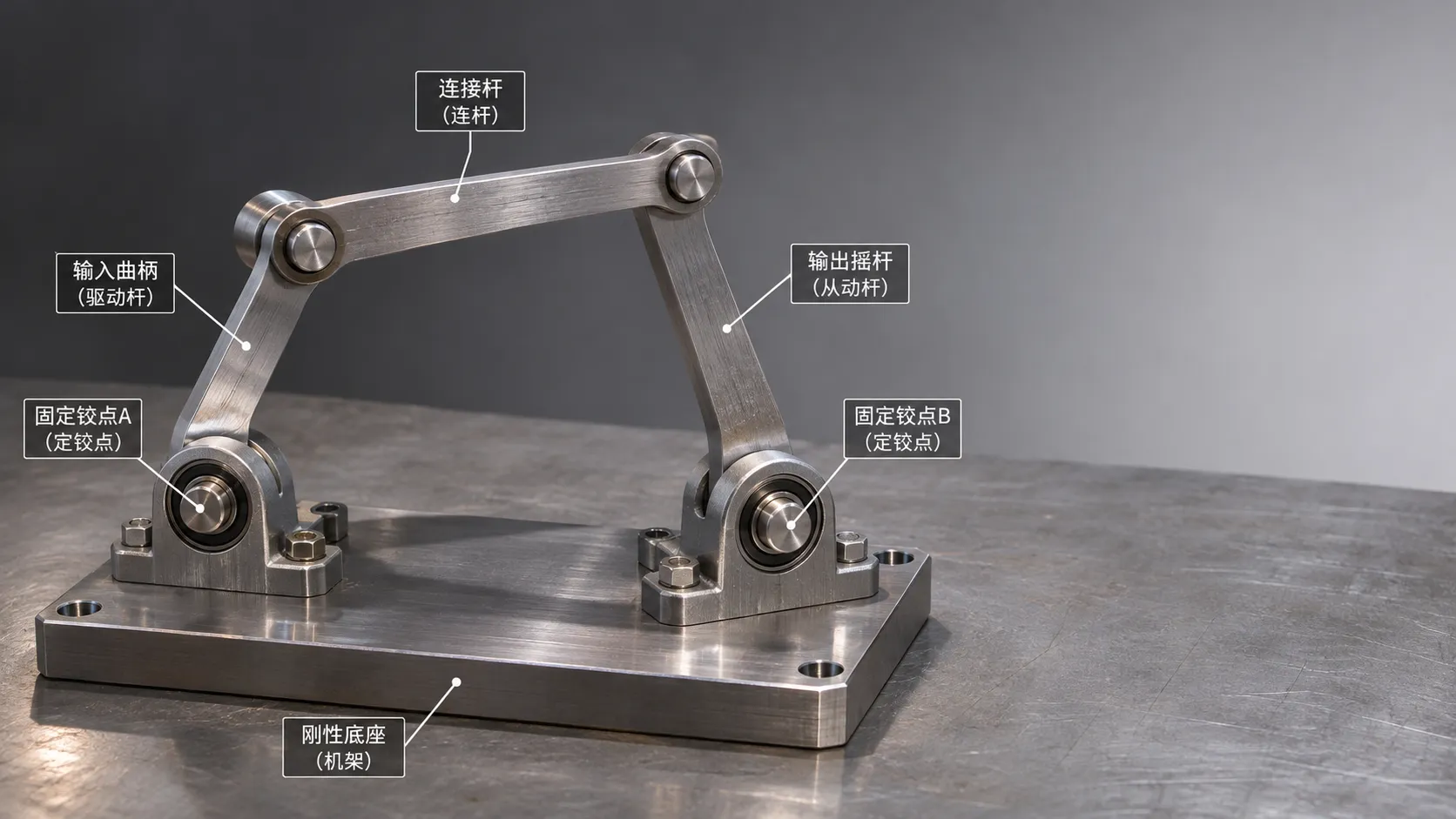
Mechanical Linkage Assemblies: How Motion and Force Are Transmitted
Explore mechanical linkage technology assemblies and learn how geometry, joints, and load affect motion, force, accuracy, and reliability.
Choosing Wear-Resistant Industrial Transmissions for Long Service Life
Choose wear resistant long life transmissions with confidence. Explore load, lubrication, sealing and supplier checks to reduce downtime and service costs.
Choosing Industrial Motion Solutions for Conveyor Speed and Load Requirements
Explore industrial motion solutions for conveyor speed and load requirements. Compare drives, torque, control and duty cycles to make a confident choice.
Chain vs. Belt Drives: How to Choose for Load, Speed, and Maintenance
Explore our industrial component knowledge base for drive selection. Compare chain and belt drives by load, speed, and maintenance to find the right fit.

Choosing Heavy Equipment for Construction: Capacity, Terrain and Costs
Choose heavy duty heavy equipment with confidence. Compare capacity, terrain, productivity, and total costs to find the right machine for your construction project.
Choosing Long-Life Timing Belts: Load, Speed and Operating Conditions
Choose long-life timing belts with confidence. Compare load, speed, environment and maintenance factors to improve reliability and reduce downtime.
Green Manufacturing Technology Costs: Upfront Investment and Payback
Explore green manufacturing technology cost, from upfront investment to payback. Learn how to assess savings, manage risks, and build a stronger business case.